
Click for larger image and other views
Magic Polishing Machine
By Red Technologies Ref: PM900
Magic Polishing Machine
The MAGIC-PM900 is an enclosed jewelry polishing machine designed for buffing and polishing jewelry and small metal parts. Buffing compound is applied to a rotating buffing wheel, and the workpiece is brought into contact with the wheel to progressively remove fine surface irregularities and produce a smooth, bright finish.
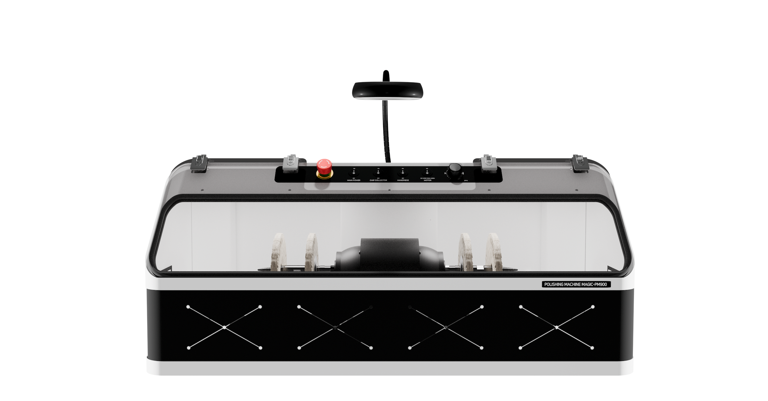 | 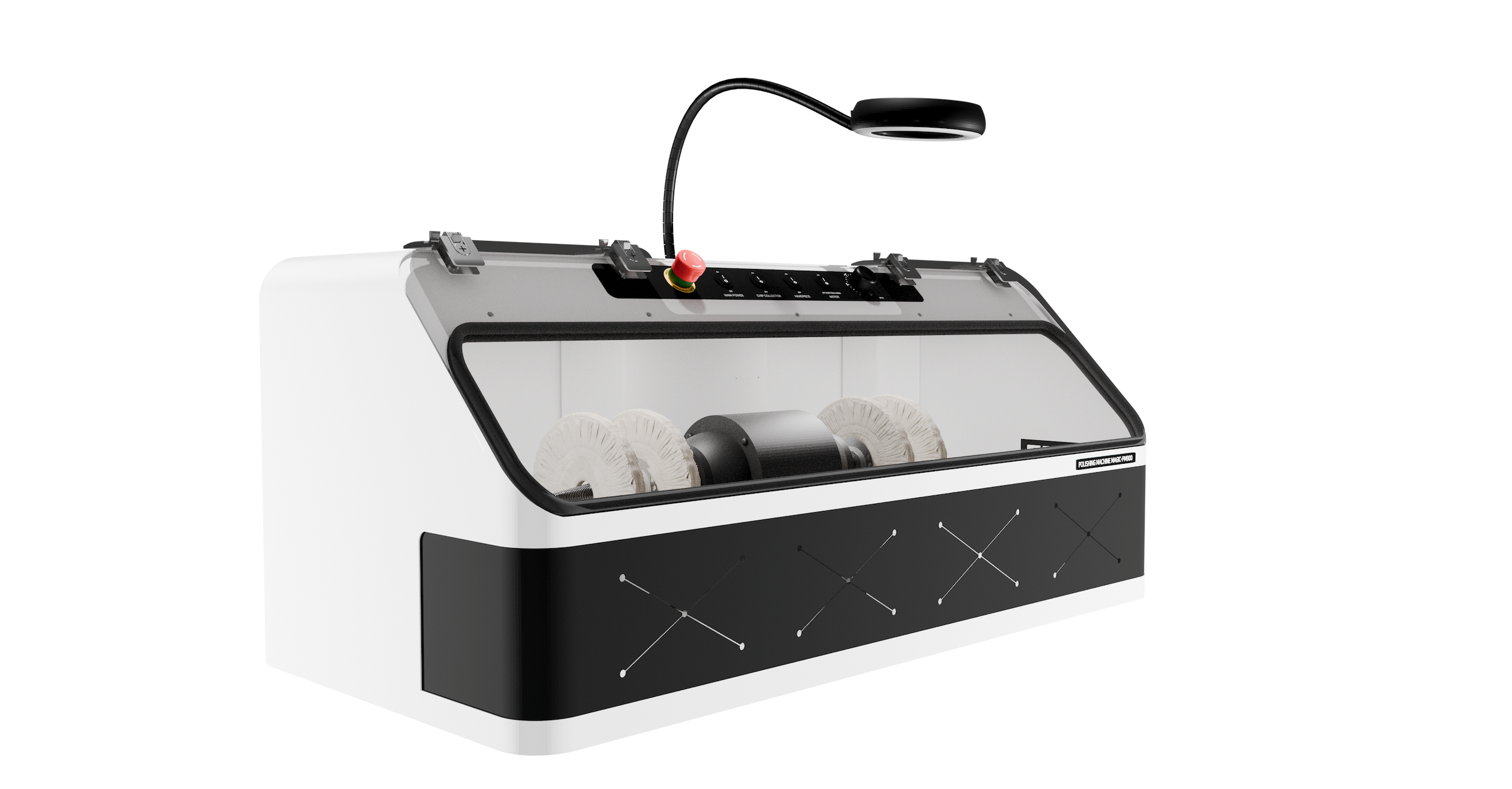 |
| Front View | Left Front View |
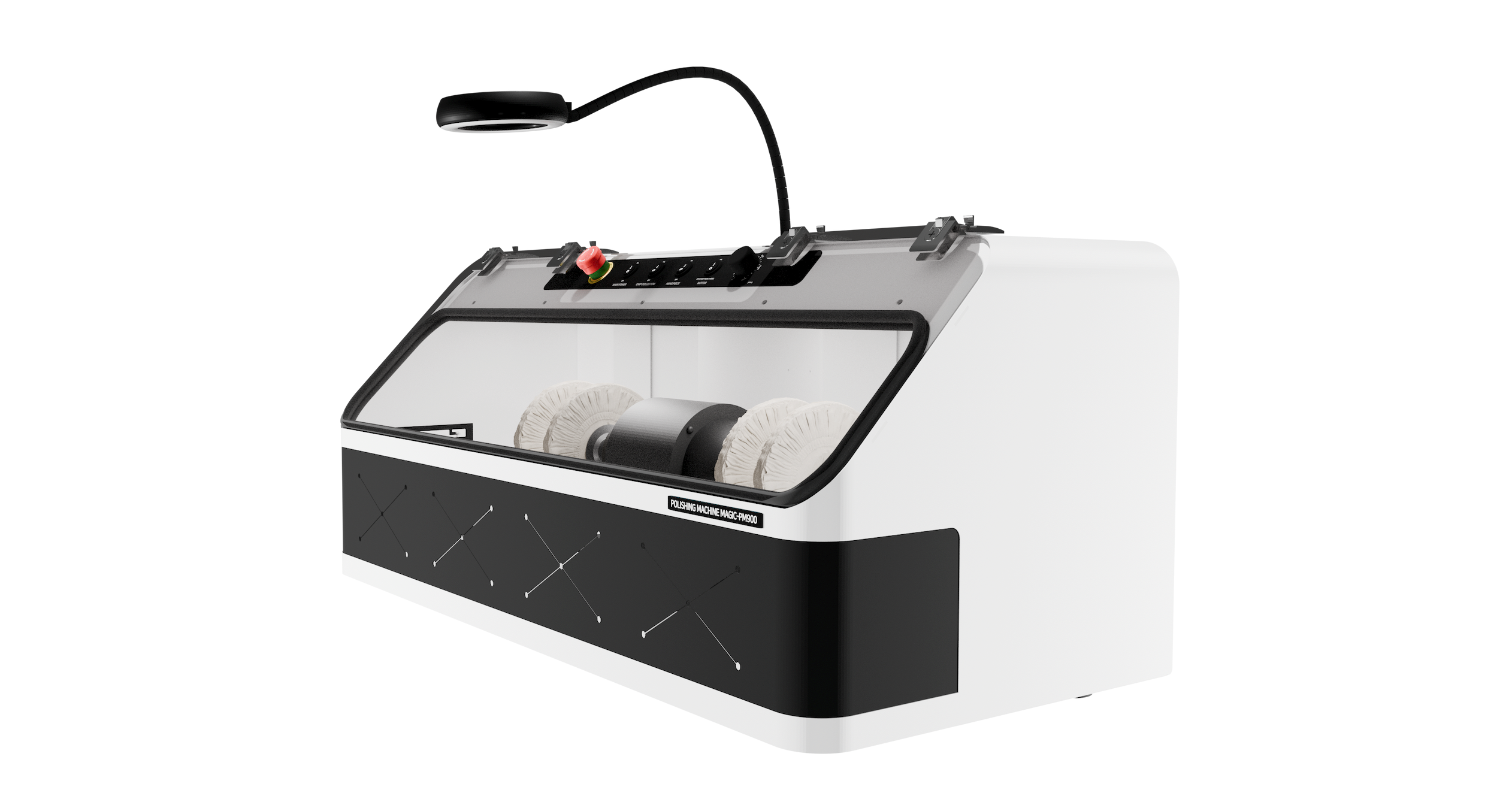 | 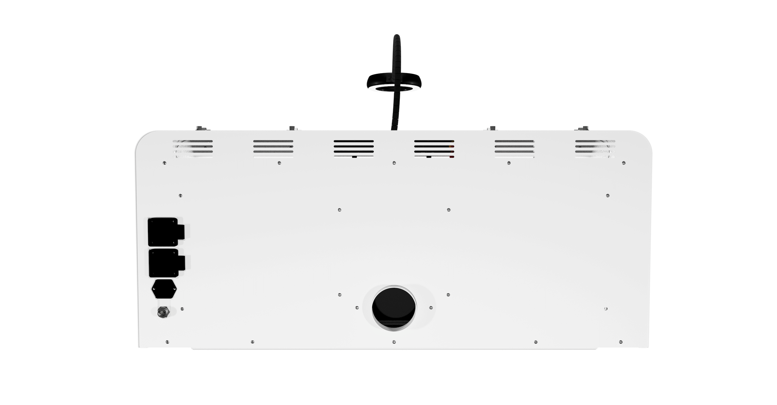 |
| Right Front View | Rear View |
• Enclosed Work Chamber: An enclosed chamber structure that helps reduce the spread of compound residue and dust outside the work area during polishing.
• Dual Buffing Configuration: Left and right buffing stations can be set up with different wheels and compounds for quick changeover between multiple polishing stages.
• 1/2 HP High-Torque Motor: Provides stable rotational force and ample performance for jewelry polishing applications.
• Torque Boost: Compensates for torque loss at low speed to maintain stable polishing performance even at low RPM.
• Variable Speed Control: Allows the wheel speed to be freely adjusted to suit the workpiece material and shape, buff type, and polishing stage.
• Foot Pedal Control: Allows the operator to control motor operation with the foot pedal while holding the workpiece securely with both hands.
• Illuminated Magnifier: Features x5/x10 dual magnification and built-in lighting, with a flexible gooseneck support for easy positioning to suit the work area.
• LED Work Light: Built-in lighting illuminates the work chamber to make it easier to inspect the polish, scratches, and residual compound.
• Dust Collector Connection & Independent Control: Exhausts dust and compound residue to an external dust collection system and allows independent dust collector control from the machine.
• Emergency Stop Switch: A safety device that quickly stops the motor in an abnormal or hazardous situation.
• Surface Finishing of Jewelry and Small Metal Parts: Buffing and polishing of gold, silver, brass, copper, aluminum, stainless steel, and other metals.
• Removal of Pre-Finishing Marks: Removes fine scratches and finishing marks remaining after casting cleanup, filing, sanding, and other preparation processes.
• Multi-Stage Polishing: Step-by-step surface finishing from intermediate Cut & Color operations through final high-gloss Coloring.
• Polish Restoration After Repair: Restores the surface finish and luster of areas affected by resizing, welding, repair, and similar work.
Deep scratches, severe casting irregularities, or major shape deformation are difficult to remove by buffing alone. First level these defects using files, sanding, rubberized abrasive wheels, or other suitable pre-finishing processes, and then buff the surface. Attempting to remove deep defects by buffing alone may over-cut the surrounding area and damage the original shape or edges.
A high-speed rotating buffing wheel can grab or eject a workpiece, and hands, hair, or clothing can become entangled in rotating parts. Read, understand, and follow all safety instructions in this section before operating the machine.
2.1 Personal Protective Equipment and Clothing
• Although the MAGIC-PM900 has an enclosed design, fine metal dust, compound particles, and buff fibers may still escape during operation. Review the SDS (Safety Data Sheet) for the workpiece material and compound being used, and wear an appropriate dust mask or respirator as required.
• Tie back or cover long hair securely. Do not wear loose sleeves, cords, necklaces, bracelets, or other clothing or jewelry that could become caught in rotating parts.
• Do not wear loose-fitting gloves, as they can become caught in the rotating buffing wheel and pull your hand into the rotating parts.
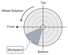
• Apply the workpiece only to the lower working area of the buffing wheel. Do not work on the top of the wheel or in an area where wheel rotation can lift the workpiece upward.
• Orient the workpiece so that sharp edges, hook-shaped features, or projections cannot catch on the buffing wheel. If such features directly oppose the wheel rotation, the workpiece may be suddenly grabbed or thrown.
• Do not allow the workpiece to contact two different points on the buffing wheel at the same time. The workpiece may become trapped or rotate unexpectedly.
• Use a holder, clamp, or dedicated jig for small workpieces or items that cannot be held securely by hand.
• Avoid conventional hand-held buffing of chains, wire, long flexible parts, and other workpieces that can wrap around the wheel. Use a dedicated jig or another suitable finishing method.
• Never exceed the maximum permissible RPM marked on the buffing wheel.
• Before changing, cleaning, or inspecting a buffing wheel, turn off the machine, disconnect the power plug, and make sure the wheel has come to a complete stop.
2.3 Dust Collection and Dust Control
• Start the dust collector before polishing. After the work is complete, keep it running briefly to remove suspended dust from inside the chamber before switching it off.
• Make sure the dust collection hose is not kinked or blocked and that the rear connection is securely fastened.
• Dust generated when working with precious metals such as gold and silver may have recovery value. Inspect the dust collection filters regularly and handle recovered material in accordance with your workshop's precious-metal recovery and management procedures.
• Some compounds can generate hazardous dust depending on their composition. Review the compound SDS and follow the required ventilation and respiratory-protection measures.
• If a workpiece becomes caught or is pulled by the buffing wheel and can no longer be controlled normally.
• If abnormal vibration, noise, odor, or smoke occurs.
• If a hand, clothing, or another object becomes caught in a rotating part and immediate stopping is required.
• If a fault is suspected in the dust collection system, power supply, or electrical system.
Before releasing the emergency stop switch, determine the cause of the abnormal condition. After all rotating parts have stopped completely, inspect the workpiece, buffing wheel condition and mounting, power supply, and dust collection system. Restart the machine only after confirming that no abnormal condition remains.
3. Specifications and Accessories
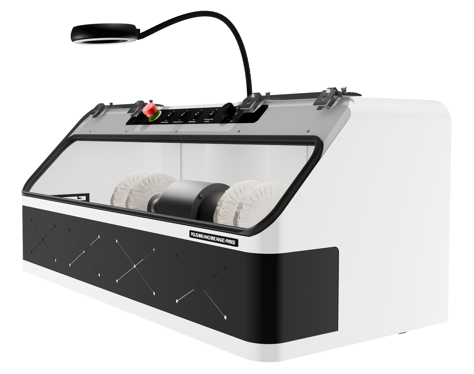
| Item | MAGIC-PM900 |
| Dimensions | 903 mm(W) x 425 mm(H) x 451 mm(D)
35.6”(W) x 16.7”(H) x 17.8”(D) |
| Power Input | AC 220–240 V, 50/60 Hz
AC 100–120 V, 50/60 Hz (USA and Japan) |
| Average Power Consumption | 500 W |
| Motor Power | 1/2 HP |
| Maximum Motor Speed | 3,450 RPM |
| Motor Shaft Diameter | Ø15.8 mm
Ø0.62” |
| Maximum Buffing Wheel Size | Ø180 mm
Ø7” |
| Dust Collection Port Diameter | Ø75 mm
Ø3” |
| Weight | 50 Kg
110 lbs |
3.1.2 Standard Accessories
| Name | Photo | Qty. | Purpose |
| Buffing Wheel Flange |  | 4 EA | Supports both sides of the buffing wheel and secures it stably to the motor shaft. |
| Nut |  | 2 EA | Clamps the flanges against both sides of the buffing wheel to secure the wheel firmly. |
| Shaft-Holding Wrench | 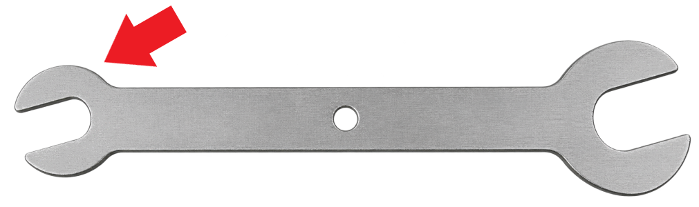 | 1 EA | Used to hold the motor shaft to prevent it from rotating.
* Wrench size: 16 mm (0.95") |
| Wheel Nut Wrench | 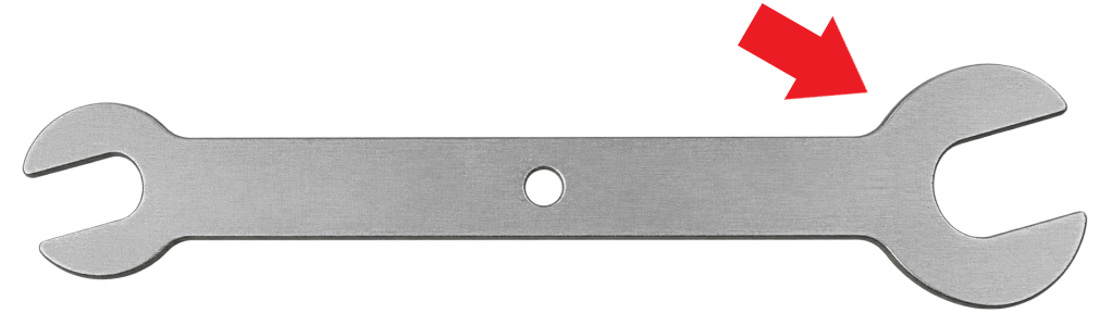 | 1 EA | Used to tighten or loosen the nut.
* Wrench size: 24 mm (15/16") |
| Foot Pedal |  | 1 EA | Foot-operated device used to control motor operation. |
| Buffing Wheel |  | 2 EA | Buffing wheels for fine and final polishing.
* Buffing wheel size: 6” |
| Power Cord |  | 1 EA | Connects the machine to an AC outlet to supply operating power. |
| Quick Start Guide |  | 1 EA | Provides quick reference for installation, basic operation, and key safety precautions. |
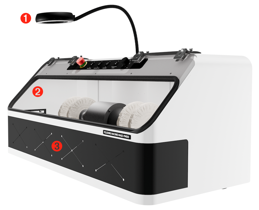
| | Name | Function |
| 1 | LED Illuminated Magnifier | A magnifier with 5×/10× dual magnification and adjustable LED illumination for easier inspection of the workpiece surface and polishing quality. |
| 2 | Transparent Protective Window | Encloses the work area to reduce the escape of dust and compound residue while allowing the operator to view the work inside. |
| 3 | Hand Port | Opening through which the operator inserts the hands holding the workpiece to bring it into contact with the buffing wheel. Do not insert your hands farther than necessary or touch a rotating buffing wheel during operation. |
| | Name | Function |
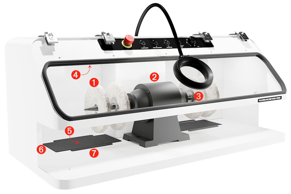
| 1 | Buffing Wheel | Different buffing wheels and compounds can be set up on the left and right sides for efficient work through successive polishing stages. |
| 2 | Motor | 1/2 HP drive motor that rotates the buffing wheels. |
| 3 | Shaft | Shaft on which the buffing wheel is mounted and secured using flanges and a retaining nut. |
| 4 | Interior Work Light | Illuminates the inside of the work chamber so the operator can easily inspect the workpiece finish, scratches, and residual compound. |
| 5 | Dust Collection Port | Suction port that captures metal dust, compound residue, buff fibers, and other debris generated during buffing and carries them to the dust collection system connected at the rear. |
| 6 | Dust Port Filter | Filter that prevents relatively large debris, such as loose buff threads or dropped workpieces, from entering the dust collection port. |
| 7 | Dust Port Shutter | Controls the suction balance between the left and right dust collection ports. Reducing the opening on one side increases suction relatively on the opposite side, allowing suction to be adjusted for the active work position. Because dust can spread throughout the chamber during operation, do not fully close either shutter; adequate airflow through both ports is needed for effective dust removal. |
| | Name | Function |
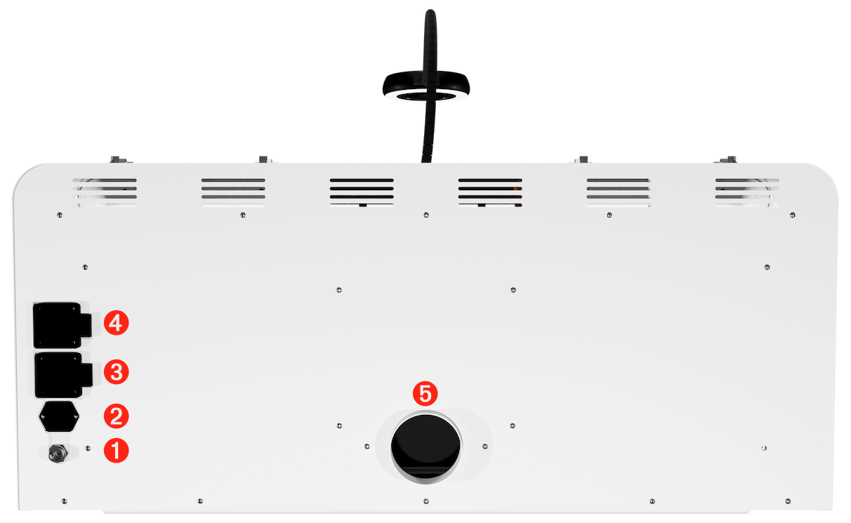
| 1 | Foot Pedal Connector | Connector for the foot pedal used to control motor operation. |
| 2 | Power Connector | Connector for the power cord that supplies AC power to the machine. |
| 3 | Handpiece Power Outlet | AC outlet for connecting and supplying power to a handpiece or other auxiliary device. |
| 4 | Dust Collector Power Outlet | AC outlet for connecting and supplying power to the external dust collector. |
| 5 | Dust Collection Hose Port | Connection port for the external dust collection hose that carries dust and residue from the chamber to the dust collector. |
5. Installation and Preparation
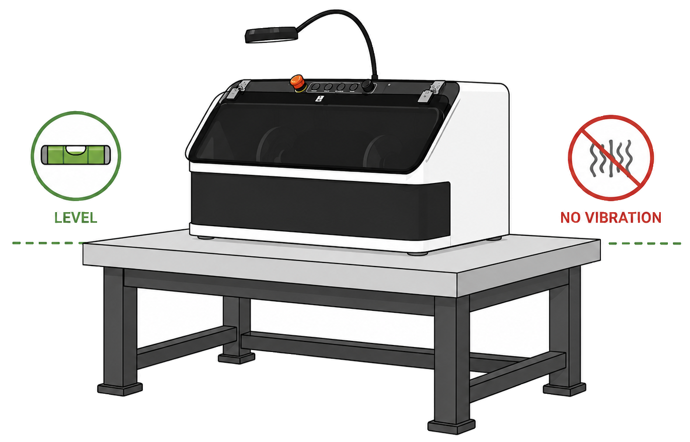
• Install the machine on a sturdy, level, vibration-free workbench. The workbench must be able to support the machine weight and withstand the forces and vibration generated during operation.
• Leave sufficient clearance behind the machine so the power cord and dust collection hose can be connected without kinking, pinching, or obstruction.
• Do not install the machine in wet or humid locations, areas with corrosive gases, locations with excessive dust accumulation, or near heat sources.
• Install the machine at a height that allows the operator to see the work area comfortably and maintain a natural working posture. Avoid positions that require excessive bending or overreaching.
• Before connecting power, make sure the supply voltage matches the rated voltage shown on the product’s nameplate.
• Fully insert the power cord into the power input port on the rear of the machine.

• Use only a properly grounded outlet with protective earth.
• Do not use the machine if the power cord or plug is damaged or deformed.
• Avoid using an extension cord whenever possible. If one is unavoidable, use a grounded extension cord with sufficient current capacity for the for the machine’s rated current.
• The foot pedal allows you to start and stop the motor with your foot while holding the workpiece with both hands, making it useful for delicate polishing of curved surfaces, edges, and detailed areas.
• Fully insert the foot pedal connector into the foot pedal connector port on the rear of the machine, then turn the coupling screw to secure it firmly.

• Place the foot pedal on the floor in a position where it can be operated comfortably and securely during polishing.


• Check the rear dust collection hose port for damage, obstruction, or foreign material.
• Push the dust collection hose fully onto the hose port and secure it firmly with a band clamp so it cannot come loose during operation.
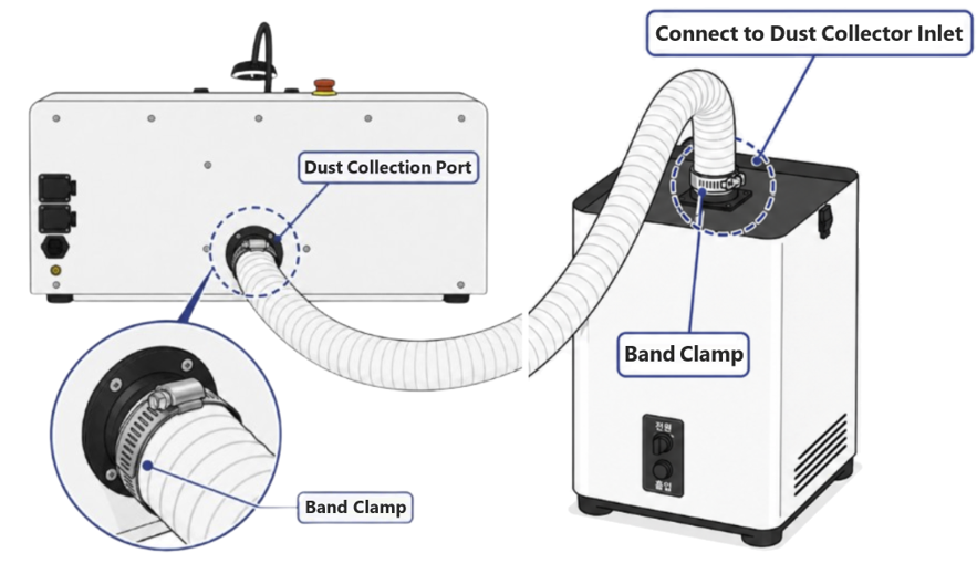
• Route the dust collection hose so it is not sharply bent, kinked, or crushed and airflow remains unobstructed.
• Make sure the dust collector filters are correctly installed and in serviceable condition.
• Run the dust collector and confirm normal suction at the internal dust ports. If necessary, adjust the left and right dust port shutters to provide suitable suction at the active work position.
• Make sure the buffing wheels are installed correctly and inspect their mounting, concentricity, and condition for damage.
• Remove all workpieces, tools, and other objects from the work chamber that could interfere with wheel rotation.
• Run the dust collector and confirm normal suction at the internal dust ports.
• Turn on the machine main power and run the motor at low speed.
• Check for side-to-side wheel wobble, abnormal vibration or rubbing noise, bearing noise, unusual odors, or other abnormal conditions.
• If no abnormal condition is found, slowly increase the speed and confirm that the buffing wheel continues to rotate smoothly and stably.
• If any abnormal condition occurs during the test run, stop the motor immediately and disconnect power to the machine. After the wheel has come to a complete stop, identify and correct the cause before repeating the test run.

• Turn off the machine and disconnect the power plug from the outlet.
• Make sure the buffing wheel has come to a complete stop before beginning.
• Open the protective window to provide sufficient access to the buffing wheel and spindle.
• Use the wrench to hold the motor shaft stationary, then loosen and remove the retaining nut or taper spindle. The left and right shafts use different thread directions; verify the loosening/tightening direction and do not apply excessive force.
• After removing the used buffing wheel, clean all metal dust and hardened compound from the flanges, adapter, and spindle. Also inspect the parts for deformation or damage.
• Mount the new buffing wheel centered on the spindle. Install the flanges and fastening components in the correct order, and do not overtighten to the point of deforming the wheel. Check the new wheel for tears, center damage, or severe eccentricity.
• After installation, rotate the buffing wheel slowly by hand to make sure it turns freely without interference with surrounding parts.
• Close the protective window, reconnect power, and perform a low-speed test run. Check for side-to-side wobble, abnormal vibration, or noise. If any abnormality is found, stop immediately and recheck the installation.
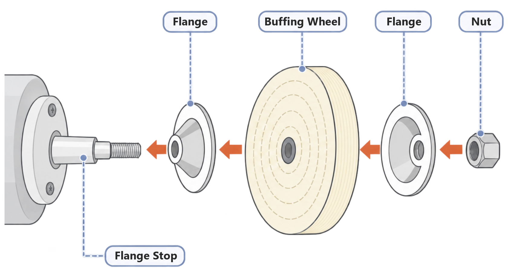
• Mount the buffing wheel so that it is properly centered on the spindle to prevent eccentricity. An off-center wheel may cause vibration and noise during operation and make stable polishing difficult.
• Label each used buffing wheel with the compound applied to it. Do not use multiple compounds on the same wheel, as mixed abrasives may reduce surface quality. Use a dedicated buffing wheel for each compound.
Four flanges can be used to mount two buffing wheels simultaneously on one side of the motor shaft. Installing wheels for different purposes together allows rapid process changeover without stopping to replace a wheel, improving work efficiency.
Install the components on the motor shaft in the following order:
Flange → Buffing Wheel → Flange → [Spacing Spacer (Optional)] → Flange → Buffing Wheel → Flange → Nut
Use the spacer only when additional clearance is required between the two buffing wheels. After installation, make sure each flange and wheel is centered accurately on the shaft and securely fastened.

- Additional flanges are sold separately.
Two flanges and a taper spindle can also be used to mount two buffing wheels on one side of the motor shaft. Installing the wheel that is changed frequently on the taper-spindle side allows quick wheel replacement without removing separate flanges and a nut, reducing changeover time.
Secure the first buffing wheel between two flanges, and mount the second buffing wheel directly onto the taper spindle.
Install the components on the motor shaft in the following order:
Flange → Buffing Wheel → Flange → Taper Spindle → Buffing Wheel
The taper spindle serves as the retaining nut for the flange, so a separate nut is not used. Screw the center of the buffing wheel onto the taper spindle until it is securely seated.

- The taper spindle is sold separately.
For either mounting method, rotate the installed wheels slowly by hand and check for eccentricity, interference, or abnormal wobble, then perform a low-speed test run. When two wheels are used simultaneously, make sure the total installed wheel width and diameter do not exceed the machine limits.
Mounting two or more buffing wheels on one side of the motor shaft can increase the possibility of cumulative centering error and eccentricity. Eccentricity may increase vibration and noise and produce an uneven finish, reducing work quality.
- Remove oil, dust, oxides, and polishing residue from the workpiece and dry it completely.
- Install the required buffing wheel and confirm the compound assigned to that wheel.
- Turn on the work light and dust collector.
- Set RPM to a low setting, then start the motor.
- Confirm that wheel rotation is smooth and free of abnormal vibration.
- Apply a small amount of compound briefly to the wheel.
- Hold the workpiece securely with both hands and bring it lightly into contact with the safe working area of the wheel.
- Keep the workpiece moving and inspect the surface frequently. Increase or decrease wheel speed as needed.
- When the stage is complete, wipe or clean the workpiece and inspect for remaining compound and scratches.
- For the next stage, use a finer dedicated buffing wheel and compound.
- When final polishing is complete, stop the motor first. Keep the dust collector running briefly to remove any residual airborne dust from the chamber, then turn it off.
• Fine dust and particles are continuously generated from the buffing wheel, compound, and workpiece during polishing. Inhaling this dust or allowing it to accumulate in the work area for extended periods can affect operator health and equipment safety.
• Always connect and operate the dust collector while using the polishing machine. If the dust hose becomes disconnected or blocked, or if suction drops noticeably, stop work immediately and inspect the hose, filters, and dust collector.

• When working indoors, provide adequate ventilation using open windows, ventilation equipment, or local exhaust ventilation. Do not use the machine in enclosed or poorly ventilated spaces.

• Even with dust collection and ventilation, fine dust may not be completely removed. Wear safety glasses and a suitable particulate respirator appropriate for the work environment, compound, and material being processed.
Perform actual buffing only in the area shown in the illustration below. Contacting the workpiece outside the correct working area may cause the wheel to grab and throw the workpiece from your hands.
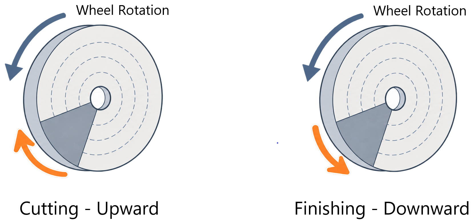
For cutting, use medium to firm pressure while moving the workpiece upward. For polishing/coloring, use light pressure while moving the workpiece downward.
• Hold the workpiece firmly with both hands whenever possible. Keeping one hand close to the point of contact with the wheel provides better control.
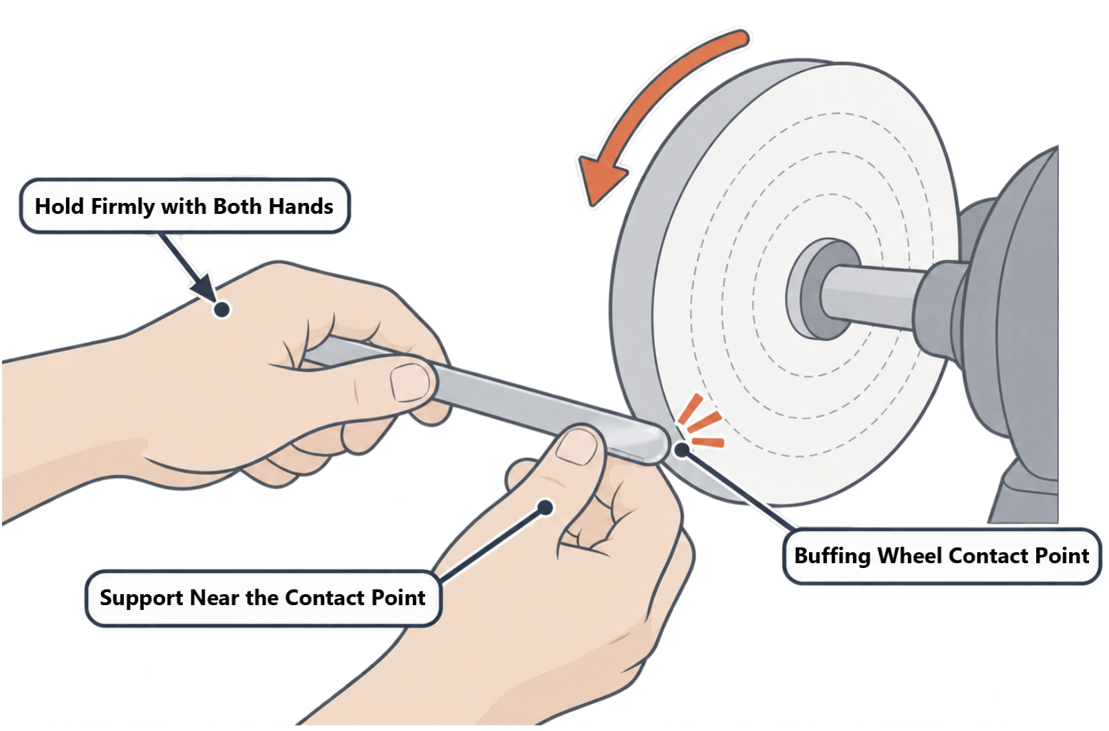
• Maintain a hand position that prevents your fingers from being pulled toward the wheel if the workpiece catches.
• Use a jig or holder for small items such as rings and small pendants.
• Orient the workpiece so that prong tips, hooks, and other thin projections cannot catch on the buffing wheel. If these features face directly against the direction of wheel rotation, the workpiece may be suddenly grabbed or thrown.
• Remove the workpiece from the buffing wheel and tilt it under the internal LED light at several angles to inspect for scratches, uniformity of polish, and surface haze.
• For closer inspection, switch on the magnifier light and inspect the workpiece surface through the magnifier.

• If heavy black residue is present with little improvement in the surface, suspect excessive compound or wheel glazing, in which the wheel face becomes smooth and hardened.
• If coarse scratches from the previous stage remain, do not proceed to a finer polishing stage. Remove the scratches sufficiently at the previous stage before moving on.
• If gray, purple, or dark reddish stains appear while polishing silver, firescale may be present. Firescale is an oxide layer or stain produced when copper in the silver alloy reacts with oxygen. Light surface oxidation can be removed by pickling in an acidic solution before repolishing. If stains remain, remove the oxidized layer sufficiently using an appropriate abrasive process before polishing.
• Repeating final polishing while firescale remains may fail to remove the stain and can make it appear more pronounced. Inspect the surface and remove the oxidized layer sufficiently before final polishing.
8. Speed, Polishing Pressure, and Work Motion
Begin at low speed. After confirming that the wheel rotates stably and the workpiece can be controlled safely, gradually increase the speed as required by the operation.

For small workpieces, thin parts, plated items, or heat-sensitive materials, begin with low speed and light pressure.
Heavy cutting generally requires a firmer buffing wheel and sufficient surface speed. However, excessively high speed increases the risk of workpiece ejection, excessive heat generation, and wheel damage.
As buffing wheel diameter increases, the surface speed at the wheel rim increases even at the same RPM. Check the wheel diameter and maximum permissible speed and set an appropriate RPM.
Reference Formula:
Surface Speed (m/s) = π × Buff Diameter (m) × RPM ÷ 60
8.2 Torque Boost and Low-Speed Operation

The PM900 Torque Boost function compensates for torque reduction at low speed and helps maintain stable drive so the buffing wheel does not stall easily when the speed is reduced for delicate work. Torque Boost is not intended to compensate for excessive work pressure; do not press the workpiece so hard that wheel speed drops noticeably.
Torque Boost is a PM900 function that helps maintain stable drive at low speed so the buffing wheel does not stall easily.

• With the MOTOR switch in the OFF position, use the foot pedal to start and stop the motor.
• When the foot pedal is depressed, the buffing wheel gradually accelerates; when the pedal is released, the wheel gradually decelerates and stops.
• The buffing wheel rotates only while the foot pedal is depressed. Press and release the pedal as needed to control wheel operation intermittently during polishing.
• Because the buffing wheel speed can be controlled by foot while holding the workpiece with both hands, the foot pedal is especially useful for delicate polishing of curved surfaces, edges, and detailed areas where quick RPM adjustment is required.
• The maximum speed reached while the foot pedal remains depressed is limited by the motor RPM setting on the control panel.
8.4 Polishing Pressure and Workpiece Movement
• Begin cutting operations with moderate pressure. Do not press so hard that the buffing wheel is excessively compressed or its rotational speed drops noticeably.
• For final polishing, maintain light pressure and move the workpiece smoothly and evenly.
• Holding the workpiece in one spot for too long can cause localized overheating or excessive cutting, which may round edges, distort the surface unevenly, or damage plating.
• Keep the workpiece moving. On broad surfaces, use a consistent pattern with slightly overlapping passes.
9. Fundamentals of Buffing and Polishing
Buffing is a finishing process in which a rotating cloth or fiber wheel repeatedly carries fine abrasive particles from the compound across the workpiece surface, removing microscopic high spots and reducing surface roughness. As surface irregularities become smaller, diffuse reflection decreases and specular reflection increases, making the surface appear brighter and more lustrous.
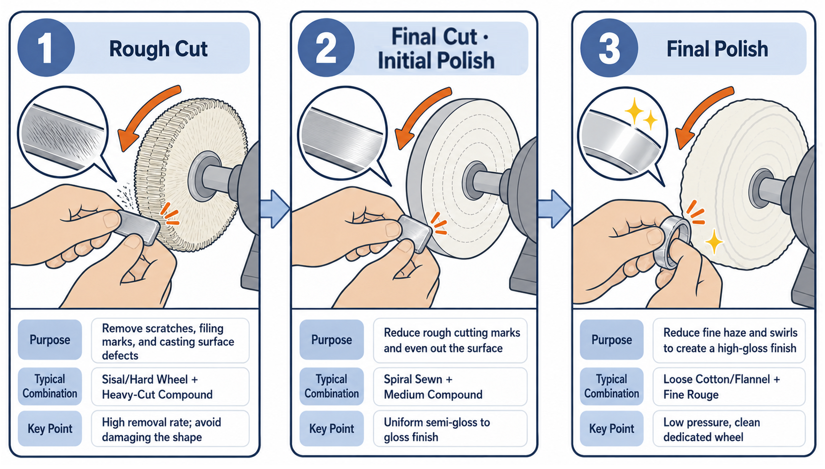
| Stage | Process | Purpose | Typical Combination | Notes |
| 1 | Rough Cut | Remove scratches, filing marks, and casting-surface defects | Sisal / Airway Hard Wheel + Heavy-Cut Compound | High material removal; take care to protect the shape |
| 2 | Final Cut / Initial Polish | Reduce coarse cutting marks and even out the surface | Spiral Sewn Wheel+ Medium-Cut Compound | Uniform satin-to-bright finish |
| 3 | Final Polish / Coloring | Reduce fine haze and swirl marks and develop a high-gloss finish | Loose Cotton / Flannel Wheel+ Fine Rouge | Low pressure; clean dedicated wheel |
Removing a deep scratch by buffing alone requires cutting away a broad area around the scratch, which can round edges and alter the shape. For efficient finishing, first level deep scratches with files, abrasive paper, rubberized abrasive wheels, or other suitable pre-finishing tools, then finish by buffing.
Adding a fine compound to a wheel contaminated with a coarse compound can leave coarse abrasive and metal particles on the wheel and create fine scratches. Whenever possible, dedicate a separate wheel to each compound and mark the compound type on the side of the wheel.
10. Buffing Wheel Selection and Care

| Buff Type | Sisal | Felt | Spiral Sewn | Airway Hard | Loose Cotton / Muslin | Canton Flannel | Airway Soft |
| Image |  |  |  |  |  |  |  |
| Characteristics | Very firm
and aggressive | Medium to firm | Medium to firm | Medium to firm | Soft and flexible | Very soft | Soft(Pleated
cotton cloth) |
10.2 Applications and Typical Compounds for Common Buffing Wheels
| Buff Type | Relative Firmness | Primary Applications | Typical Compounds | Use Notes |
| Sisal | 5/5 Very High | Rough cutting, removal of light filing marks and scratches, pre-finishing before polishing | Black/Emery, Greaseless, heavy-cut compounds | High material removal; avoid over-cutting edges, thin parts, and plated items |
| Felt | 3/5 Medium | Precision polishing of flat areas, edges, and localized areas | Medium-to-fine compounds, Greaseless, material-specific polishing compounds | Good shape retention, but localized cutting and heat can be high; use controlled pressure |
| Spiral Sewn | 4/5 High | Medium cutting, removal of cutting marks, initial polishing, Cut & Coloring | Brown/Tripoli, medium cut & coloring compounds, White/Green depending on material | Versatile; firmness varies with stitch spacing and treatment |
| Loose Cotton / Muslin | 2/5 Low | Fine polishing, final polishing, and detailed work on curves, grooves, and recessed areas | Red/Blue, Extra Fine Green, fine coloring compounds | Use dedicated wheels by process to prevent cross-contamination between compounds |
| Canton Flannel | 1/5 Very Low | Final high-gloss polishing and Coloring of gold, silver, and other precious metals | Jeweler's Rouge, Red/Blue, and other fine compounds | Intended primarily to develop luster rather than remove material; use a clean dedicated wheel |
| Airway Soft | 3/5 Medium | Intermediate-to-final polishing and Coloring of soft non-ferrous metals | White/Green and fine compounds suited to the material | Not limited to final polishing; depending on wheel specification, it may also be used for Cut & Coloring |
| Airway Hard | 4/5 High | Initial cutting, medium cutting, Cut & Coloring | Black/Emery, Greaseless, cut & coloring compounds | Cutting action varies with the treatment and firmness of the cotton cloth; do not assume the same cutting action as sisal |
11. Selecting and Using Buffing Compounds
Bar-type buffing compound is a solid material containing abrasive particles and binder. When lightly applied to a rotating wheel, frictional heat softens the surface and transfers a thin abrasive layer to the buff. Actual cutting action depends not only on abrasive particle size but also on wheel firmness, speed, and pressure.

| Type | Cutting Action | Typical Applications | Recommended Buff | Notes |
| Black / Emery Compound | Heavy to Very Heavy | Initial cutting on stainless steel, iron, and similar metals; removal of scratches, pits, and coarse finishing marks | Sisal, Airway Hard, firm Spiral Sewn | Typical Rough Cut family; not suitable for final polishing |
| Brown / Tripoli Compound | Medium | Cut & Coloring of non-ferrous metals such as brass, copper, aluminum, and zinc alloys | Spiral Sewn, Airway | Widely used for intermediate finishing of non-ferrous metals. Traditional Tripoli may contain crystalline silica; review the SDS before use. |
| White Compound | Light to Medium | Removal of fine scratches and intermediate-to-final polishing. Some products are used on stainless steel, steel, nickel, and chrome. | Spiral Sewn, Loose Cotton, Airway Soft | Formulations vary greatly by manufacturer. Some White compounds are intended for plastics or resins, so always confirm the stated application. |
| Red Compound | Almost None to Very Light | Final high-gloss polishing of gold, silver, and other precious metals | Loose Cotton, Canton Flannel | A classic jewelry final-polishing family; use a separate clean dedicated buff |
| Blue Compound | Almost None to Light | Final polishing and high-gloss finishing of gold, silver, and fine surfaces | Loose Cotton, Flannel | Depending on the manufacturer, Blue may be formulated as a general-purpose polishing compound |
| Green Compound | Fine to Light Cutting (varies by product) | High-gloss finishing of stainless steel, platinum, chrome, and hard alloys | Loose Cotton, Spiral Sewn, Canton Flannel | Commonly used on hard metals and stainless steel, but some formulations are general-purpose or intended for non-ferrous metals |
| Greaseless Compound | Heavy to Fine, Depending on Grit | Leveling casting surfaces, removing machining marks and scratches, blending, satin finishing, and edge breaking | Sisal, Spiral Sewn, Loose Cotton, Felt | Unlike conventional wax-based compounds, an adhesive and abrasive form an abrasive coating on the wheel face. Mainly used as a pre-finishing process before polishing. |
| Cut & Color Compound | Medium to Heavy | Combines cutting and coloring in one operation on iron, stainless steel, aluminum, brass, and other metals | Spiral Sewn, Airway | A major category of modern industrial compounds; select by the product's Cut/Coloring performance grade rather than color alone |
| Stainless Steel / Hard-Metal Compound | Medium to Fine, Depending on Product | From pre-finishing through final high-gloss polishing of stainless steel and hard alloys | Sisal / Spiral Sewn → Loose Cotton | It is more accurate to treat stainless-steel/hard-metal compounds as a material-specific family rather than assuming Green alone represents all stainless-steel compounds |
Do not determine compound performance by 'color' alone. Color and formulation systems vary among manufacturers. Always check the product label, SDS, and manufacturer-recommended applications.
11.3 Applying Compound - 'Little and Often'

- Make sure the buffing wheel is clean and properly opened/fluffed.
- Start the dust collector and motor and allow the wheel to reach a stable operating speed.
- Briefly touch the bar compound to the working face of the wheel. Begin with short applications of approximately 0.5–2 seconds and adjust to the actual wheel size and speed.
- Reapply a small amount when cutting action decreases during work.
- If the wheel face becomes glossy or excessive black residue appears, too much compound may be present. Dress the wheel with a rake and restart with a small amount.
Applying more compound does not increase cutting action proportionally. Excess binder can make the wheel face slick, reducing cutting action while increasing heat and contamination.
• Use only one type of compound on each buffing wheel. Using different compounds on the same wheel can mix abrasive particles, create scratches, and reduce final-polish quality.
• When storing used buffing wheels, mark the compound type on the side of the wheel or at the storage location to prevent mix-ups.
• Store final high-gloss wheels separately from rough-cut and intermediate-polishing wheels. Coarse abrasive particles or metal dust can cause fine scratches or surface haze.
12. Recommended Processes by Material and Work Condition
The table below provides a starting point for applying common buffing wheel and compound combinations to the PM900 workflow. Results may vary with alloy composition, plating thickness, heat-treatment condition, surface roughness, and buff manufacturer. Always test on a small area first.
| Material | Condition | Buff | Compound | Starting Speed | Cautions |
| Gold / Silver / Precious Metals | Good Surface Condition | Loose Cotton / Flannel | Red/Blue | Low | Light pressure; dedicated wheel |
| Gold / Silver / Precious Metals | Fine Scratches | Soft Spiral Sewn → Loose Cotton | Fine Intermediate Compound → Red/Blue | Low to Medium | Prioritize shape preservation |
| Brass / Copper | General Finishing Marks | Spiral Sewn → Loose Cotton | Brown/Tripoli → Rouge | Medium | Remove oxide film before buffing |
| Aluminum | General Finishing Marks | Spiral Sewn → Loose Cotton | Tripoli/Brown → Fine Compound | Medium | Watch for heat buildup and discoloration |
| Stainless Steel | Coarse Scratches | Sisal / Airway Hard → Spiral Sewn → Loose Cotton | Black → White/Green | Medium to High | Skipping stages may leave scratches |
| Stainless Steel | Final Polish | Loose Cotton / Airway Soft | Green Extra Fine | Medium | Use a clean dedicated wheel |
| Nickel / Chrome Plating | Good Surface Condition | Soft Spiral Sewn / Loose Cotton | White or Fine Rouge | Low | Avoid cutting through the plating |
| Thin Plated Items | Final Polish | Soft Loose Cotton / Flannel | Red/Blue | Low | Do not use aggressive cutting stages |
| Cast / Rough Surface | Casting Marks / Surface Irregularities | Sisal / Spiral Sewn | Greaseless Compound Sequence | Medium | Confirm shape retention before proceeding to polishing stages |